Technical information
- Specifications
Products
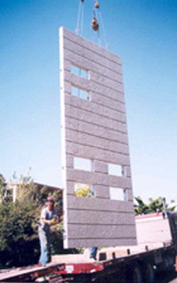
Can be designed as Cladding or engineered to transfer shear
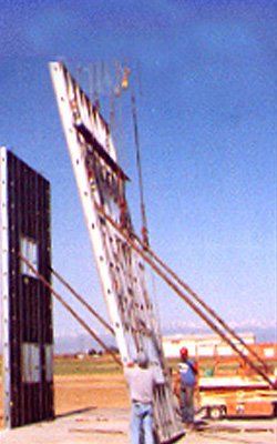
can be fabricated on site using common tilt-up procedures.
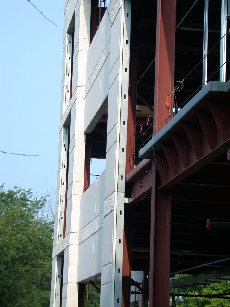
With 33% of energy loss in the U.S. occurring through heating, cooling and operating commercial buildings
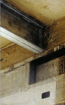
MSC floors and roofs can be engineered from light-gauge steel joists.
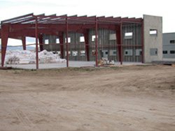
MSC panels are ready for utilities and insulation in stud cavities..

MSC panels integrate light-gauge metal framing with thin-shell.
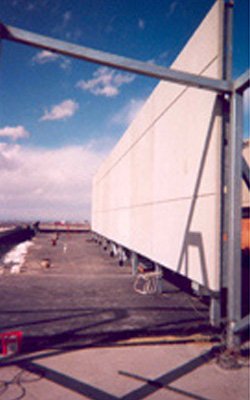
Light-weight MSC concrete panels are fabricated to match the texture.
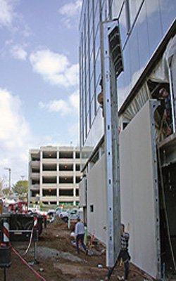
Lighter weight Metal Stud Crete® panels may contribute toward achieving additional LEED points
Technical Information
Metal Stud Crete® load bearing, structural shear wall system has current testing and approvals from nationally recognized testing laboratories and conforms to building codes World Wide through the ICC ESR- 2511 engineering report, and the IBC .
(See all of our technical information and MSC details on the following pages) Click on the links to open up the PDF files.
e-mail request to: info@metalcrete.com
Technical Reports
1. Standard Web and Track Connectors
2. Air Gap Web and Track Connectors 8-22-20
3. Air Gap Web and Track Connectors
4. Air Gap Corner Wrap
5. Air Gap Corner Detail
6. MSC Wall Plan View
7. MSC Web Connector to Stud
8. MSC Track Connector to Stud
9. Reveal Detail [TYP]
10.Panel to Panel [SW] Condition 1
11.Panel to Panel [SW] Condition 2
12.Lap Joint Detail [C] Condition
13.MSC Wall A T Header and Sill
14.MSC Wall with Concrete Return at Window
15.MSC Wall Door Frame Cast In
16.MSC Wall Concrete Return at Door
17.MSC Wall at Connection to Slab
18.MSC Wall to Stepped Slab
19.MSC Wall Corner Conditions
20.Returned Outside Corner
21.Outside Corner with Fin Lap
22.Metered Outside Corner with Fin Lap
23.Solid Concrete Metered Corner
24.Outside Angeled Corner
25.Inside Angeled Corner
26.Inside Butt Joint [SW]
27.Inside Butt Corner
28.Concrete Bond Beam at Floor or Roof
29.Concrete Beam with Weld Plate
30.Wood Ledger to Concrete Beam
31.Steel Embed for Beam Saddle
32.Concrete Column and Beam Detail
33.MSC Wall to T.S. Beam at Window Head
34.MSC Wall to T.S. Beam at Window Sill
35.MSC Bond Beam to T.S. Beam
36.MSC Wall with Fin at T.S. Column
37.MSC Wall with Stud Beam Pocket
38.MSC Shear Transfer to Roof Diaphragm
39.Steel Channel Ledger with Verti Clip
40.Sheet Metal Cap at Parapet
41.Concrete Return at Top of MSC Panel
42.Steel Stud Parapet Detail
43.Top Chord Bearing Truss on T.S. with Concrete Parapet Fin
44.Angeled Truss Bearing on T.S.
45.MSC Wall Mid Span Connection to Floor
46.Spandre Connection to Floor Option 1
47.Spandrel Connection to Floor Option 2
48.MSC Wall Spandrel Detail at Deck
49.MSC Wall with Beam Connection to Floor
50.MSC Wall with Upper or Lower Fin at Floor
51.MSC Wall Clading to Pemb Strucutre
52.MSC Shear Wall to Pemb Strucutre
53.MSC Wall End Column Condition
54.MSC Wall End Condition with Box Studs
55.MSC Wall Double Sided with Concrete Return
56.MSC Wall with Architectural Detail
57.MSC Wall Connection to Block or Concrete Wall
58.MSC Wall In-Out Connection at Beam or Column
59.MSC Wall In-Out Connection at Floor
60.MSC Wall In-Out Connection at Floor and Beam
61.SC Wall Load Bearing Connection at Beam
62.MSC Wall Load Bearing at Either Side of Column
63.MSC Wall with Verti Clip Connection to Steel Beam
64.MSC Composite Floor or Roof Cast in Place Option 1 Single Joist
65.MSC Composite Floor or Roof Cast in Place Option 2 Double Joist
66.MSC Composite Floor or Roof Pre-Cast


